Home / documentation / LCD CONTROL - 1.0.0

LCD CONTROL

LCD CONTROL

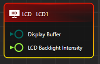
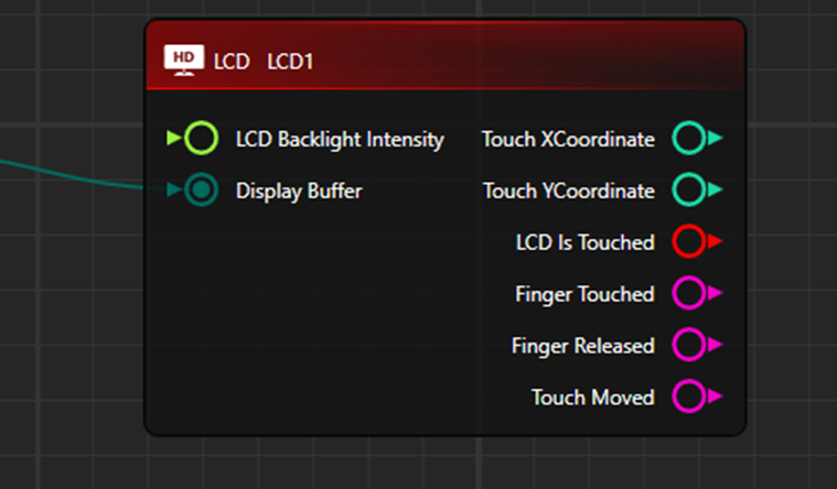
1. Default Node Display
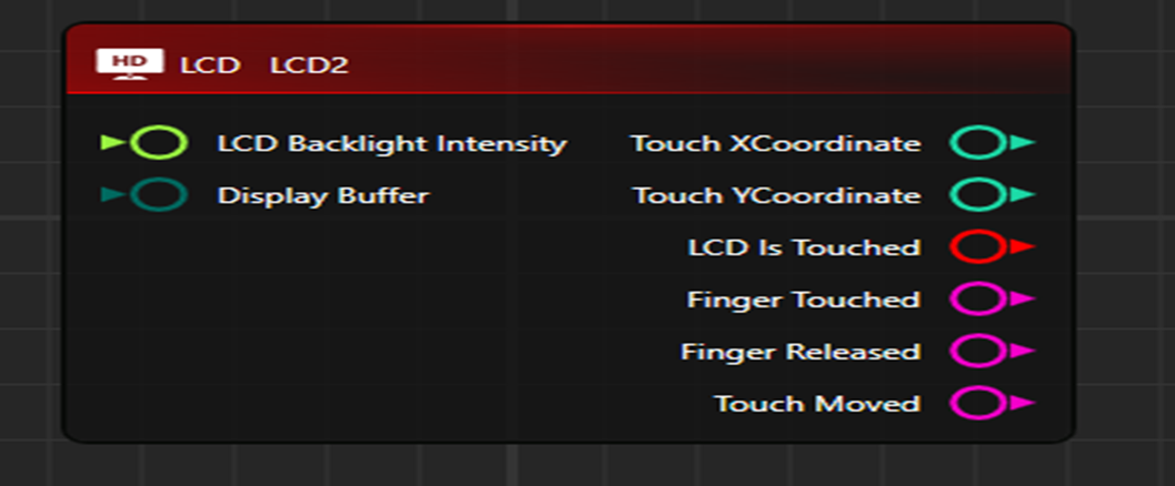
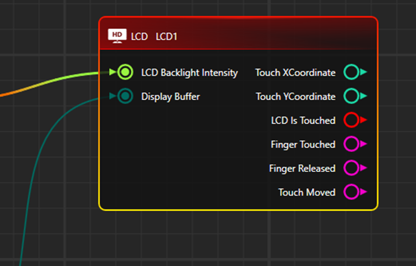
Different ports are:-

      • Display Buffer : It is of “ByteArrayDriver” type port.it is used to pass image array as data.
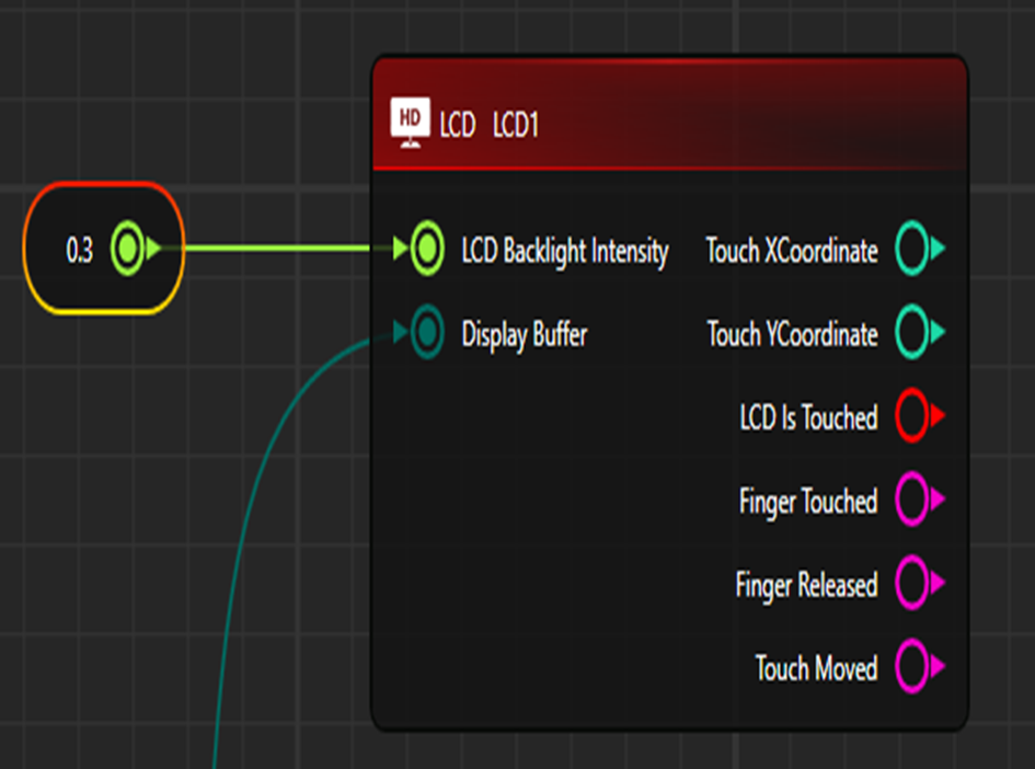
      • LCD Back Light Intensity : It is of “FloatTypeDriver”.it is used to increase or decrease the intensity of the backlight light color. Backlight color is set through “Property Window”.
      • Touch XCoordinate: It is of “IInt32Driver”.It will provide the value of X-Coordinate.
      • Touch YCoordinate: It is of “IInt32Driver”.It will provide the value of Y-Coordinate.
      • LCD Is Touched: It is of “IBoolTypeDriver”.
      • Finger Touched, Finger Released, Touch Moved: These are “ActionEvent” ports.

2. Property window default Display
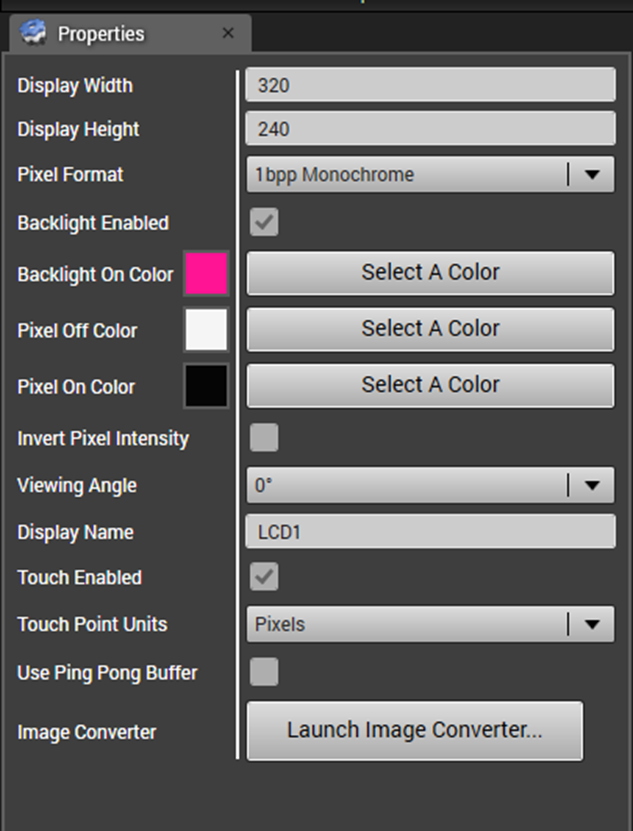
    • Display Width/Display Height: Used to set Image display Dimension on LCD Control.
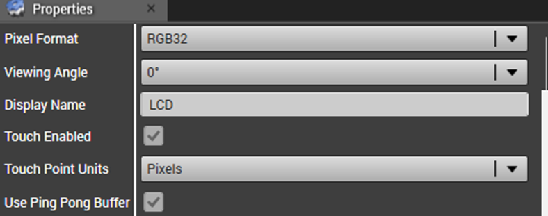
    • Pixel Format :It is used to set type of Image format. Available options are 1bpp Monochrome,4bpp Monochrome,8bpp Monochrome,RGB565,RGB32,RGB24. If Pixel format is other than 1bpp Monochrome,4bpp Monochrome,8bpp Monochrome then On Node “LCD Backlight Intensity” Port option will not be visible.


    • Backlight Enabled: This options is available for only Monochrome Image type. If it is checked then the Image Background color will be displayed according to the set color. If it is unchecked then only the default background color will be visible on the image.
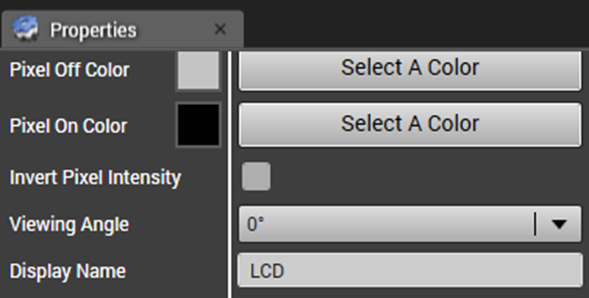
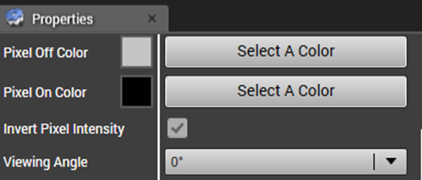
    • Pixel Off Color/Pixel On Color: In a Monochrome image, only two colors can be set. so these properties help in setting the on/off color of the pixels.
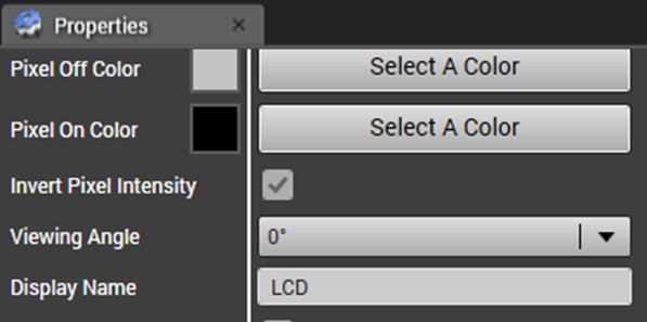
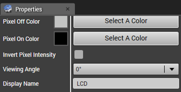
    • Invert Pixel Intensity: It is a Checkbox. It will be unchecked as default. if it is unchecked then the Intensity of the Set background color will be “1”, until and unless through the “LCD Backlight Intensity” port another value is not supplied.
      • if it is unchecked and value is supplied then the intensity of the background color on the image will get either decreased or increased according to the supplied values.
      • If it is checked then default value will be 0, until and unless through the “LCD Backlight Intensity” port another value is not supplied. if through “LCD Backlight Intensity” port values are supplied then its impact on the Displayed image will be like (1-Supplied value).

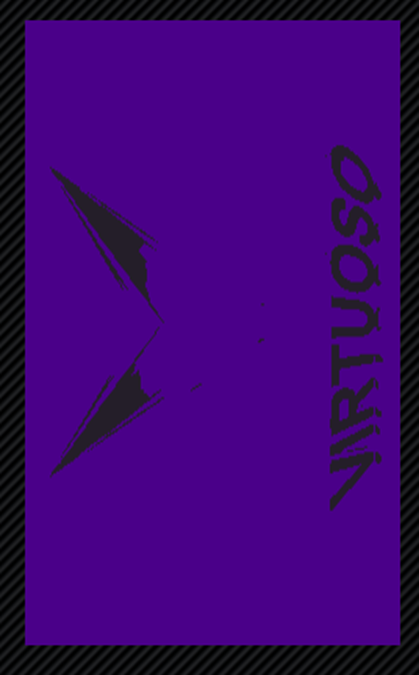
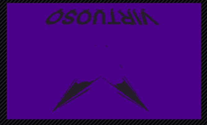
    • View Angle:-It will rotate the image as according to the selected value.
    • If view angle is “0”, then image will be like follow.

    • If View angle is “90 CW” then image will be as follows.

    • If View angle is 90 CCW, image will be as follows.

    • If View angle is 180, image will be as follows.

Display Name: It is used to give name to the LCD Control.

Touch Enabled: It is a checkbox. if it is checked then touch-related ports will be visible on the Node.
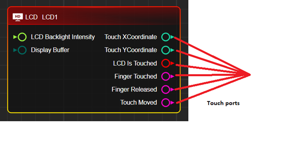
If it is unchecked, Node will have the following display.
Use Ping Pong Buffer: It is a checkbox. if it is checked then Node will have the following display.
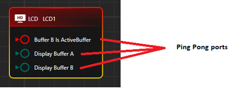
Image Converter: It is a special type of tool that converts Images into ByteArray. Image can be converted into specified width and height with different pixel formats.


3. Preview Window display 

A) In Monochrome Pixel Format
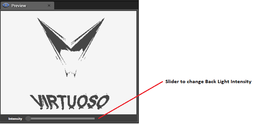
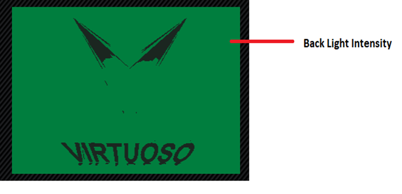
Preview helps to see the image with Back light intensity.

B) In RGB Pixel format


 4.Test cases

(i) When “Invert Pixel Intensity” checkbox option in the property window is Unchecked.Image with default Backlight color can be seen. This time “LCD BackLight Intensity” port value will be “1” by default.
Expected Result:-

(II). When “Invert Pixel Intensity” checkbox option in property window is checked. This time “LCD BackLight Intensity” port value will be “0” by default.
Expected Result:

(iii)  When “Invert Pixel Intensity” checkbox option in the property window is Unchecked, But from the “LCD Backlight Intensity” value is supplied, the Image backlight intensity value will be the same as supplied value. It can be compared with a preview window image.
Expected Result:

(iv)  When “Invert Pixel Intensity” checkbox option in property window is checked,But from “LCD Backlight Intenesity” port any value is supplied,Image backlight intensity value will be (1-SuppliedValue).It can be compared with preview window image.
Expected Result:-Backlight Intensity of the image will either increase or decrease as according to the supplied value.

Note:-Backlight Intensity scale lies between 0-1.

(A) When supplied value is “0”

(B) Supplied value is “0.5”

(C ) When supplied value is “1”

(IV) Images for different Pixel format with Backlight Intensity value=1

(A) 1bpp Monochrome

(B) 4bpp Monochrome

(C) 8bpp Monochrome

(D)RGB565

(E) RGB32

(V)Use of Ping Pong Buffer

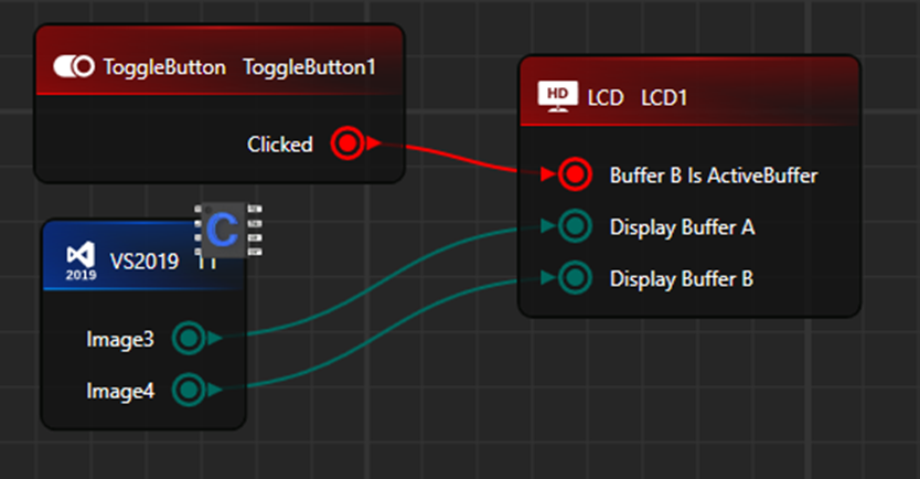
If in property window “Ping Pong Buffer” checkbox is checked.
It will work if “Buffer B Is ActiveBuffer” port is supplied with any Boolean value.if Boolean value is true then image of “Display Buffer B” will be visible else “Display Buffer A” image will be visible.
Expected Result:

Example-Display Buffer A(Image)

Example-Display Buffer B(Image)
On this page: